
DAF Dissolved Air Flotation
Separating suspended solids, oil & grease and colloidal particles by floating them with micro air bubbles.
What Is DAF Technology?
DAF (Dissolved Air Flotation) is based on the principle that water is saturated with air under pressure and then released to atmospheric pressure, so that the resulting micro-bubbles (typically 30-50 µm, 20-80 µm in the wider range) attach to suspended particles and carry them in exactly the opposite direction to settling, that is, up to the surface. Light solids that do not settle in water, or settle only very slowly — oil & grease, colloids, fibre, dye flocs — are separated by flotation within minutes.
The purpose of this article is not to sell but to explain: what is the physics underlying DAF, how does a micro-bubble lift a particle, what does the A/S ratio mean and with which design parameters is a DAF unit sized? In short, we address the question "what is happening inside the box" at engineering depth. The numerical ranges given are typical orders of magnitude found in the literature; the exact values for each plant are determined by wastewater analysis and jar testing.
Looking for the product, the series and capacities? This page explains the technology. For sector-based inlet-outlet tables, GESU DAF series and the enquiry process, see the product page: GESU DAF Systems → · For the selection decision: DAF or Sedimentation?
Working Principle
Micro-bubble Generation
Water saturated in the air dissolution vessel at a typical pressure of 4-6 bar passes through the nozzles and forms 20-80 µm micro-bubbles.
Flotation
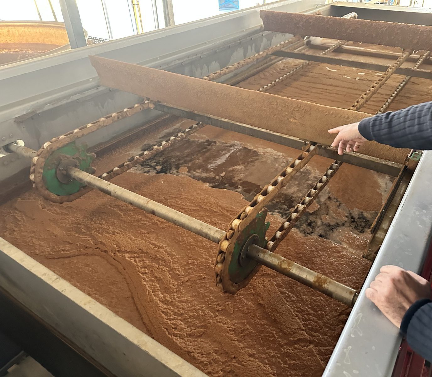
The bubbles attach to floc particles and carry them to the surface. The surface sludge is collected by the skimmer.
Recirculation
20-50% of the effluent is sent back to the air dissolution vessel as recirculation.
The Physics of Flotation: Why Does a Particle Float?
Sedimentation tries to bring the particle down to the bottom by gravity. Flotation, on the other hand, makes the effective density of the particle lighter than water and lifts it upwards. Three steps make the difference.
Rise velocity — the Stokes' law context
According to Stokes' law, the rise (or settling) velocity of a particle/bubble in still water increases approximately with the square of its diameter and with the density difference between it and the fluid, and decreases with the viscosity of the water. In sedimentation the settling velocity of small, light colloids is almost zero; that is why hours of retention are needed. Flotation reverses this equation: once an air bubble is attached to the particle, the average density falls below that of water and the rise velocity becomes positive, and moreover large.
Bubble-particle attachment
A collision and then an attachment must take place between the micro-bubble and the floc. The probability of attachment depends on how hydrophobic the particle surface is, on how small the bubble is and on how low the turbulence is. Coagulation-flocculation is decisive here: unless the charge is neutralised and the surface made suitable, the bubble cannot hold on to the particle and stays free (white water). A well-prepared floc practically traps the bubble.
The A/S ratio — the air/solids balance
The most fundamental design quantity of the system is the A/S ratio (air-to-solids): the mass of dissolved air supplied per unit mass of suspended solids. If there is not enough air, part of the solids cannot be floated; too much air causes a waste of energy and turbulence (which breaks up the attachment). Typical A/S values in the literature are given in the range of about 0.005-0.06 kg air / kg solids. A/S is a result determined jointly by the saturation pressure, the recycle ratio and the feed solids concentration — these three are linked to each other in the table below.
The physics in summary: DAF brings together the trio of small bubbles (high attachment) + the right chemistry (stable attachment) + sufficient air (A/S). If any one of the three is missing, efficiency drops — and most problems arise precisely from an imbalance in this trio.
Why Is the Bubble Size 30-50 Microns?
Bubble size is the hidden adjustment knob of DAF. Neither too small nor too large is wanted; there is a "sweet spot" in between.
Too small (<20 µm)
The attachment probability is high, but the buoyancy (rise velocity) decreases. The bubbles remain suspended in the water without reaching the surface — the risk of "white water" and TSS carry-over.
Sweet spot (~30-50 µm)
Many bubbles and a large total surface area per unit volume of air → high collision/attachment. At the same time a sufficient rise velocity → the floc-bubble aggregate is carried safely to the surface.
Too large (>100 µm)
They rise quickly but are few in number, with a small total surface area → a low probability of attachment. They may also create turbulence as they rise and break up the freshly formed flocs.
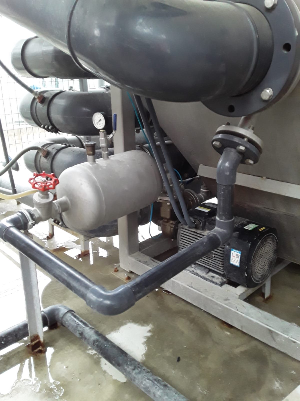
This size is created as the saturated (air-loaded) water passes through the pressure release nozzle/valve with a sudden expansion: the air dissolved at high pressure suddenly nucleates at atmospheric pressure and turns into millions of micro-bubbles. The nozzle design, the saturation pressure and the recycle flow together determine this size and the bubble density. If the nozzle wears or drifts out of adjustment, the bubble distribution deteriorates — a common but often overlooked cause of a drop in efficiency.
DAF Design Parameters
Sizing a DAF unit means solving the parameters below in an interdependent way. The values are typical ranges quoted in the literature; the exact design is determined by the wastewater character, the flocculability and the target efficiency.
| Parameter | What It Expresses | Typical Range (literature) | What It Affects |
|---|---|---|---|
| Hydraulic surface loading | Flow per unit tank surface area (m³/m²·h) | Typically ~4-10 m³/m²·h* | If exceeded, the floc-bubble aggregate escapes to the outlet before reaching the surface (TSS carry-over) |
| Solids loading rate | Solids mass per unit surface area (kg TSS/m²·h) | Varies with the wastewater | Determines the thickness of the float layer and the skimming capacity |
| A/S ratio | Air mass / solids mass | Typically ~0.005-0.06 kg/kg | Flotation adequacy; if low, efficiency drops, if high, energy is wasted |
| Saturation pressure | The pressure at which air is dissolved in water (Henry's law) | Typically ~4-6 bar | The amount of dissolved air, and therefore the bubble density and A/S |
| Recycle ratio | The share of effluent that is saturated and fed back to the inlet | Typically ~20-50% | The total dissolved air supplied; as it rises, the effective hydraulic load rises too |
| Retention time | The time the water stays in the flotation zone | Typically ~5-15 min | The time needed for the bubble-floc aggregate to reach the surface |
| Bubble size | The micro-bubble diameter formed at the nozzle | Typically ~30-50 µm | The balance between attachment probability and rise velocity |
*A lamella (plate pack) DAF can operate at an appreciably higher hydraulic load on the same footprint, because the inclined plates enlarge the effective separation surface. All values in the table are typical literature orders of magnitude, not a commitment; the final sizing is done with a water analysis and a jar test.
Chemical Conditioning Ahead of DAF
The efficiency of a DAF is largely decided before the water enters the tank. If there is no solid floc for the bubble to attach to, even the best air system will not do the job. That is why DAF is almost always designed together with coagulation-flocculation.
Coagulation (charge neutralisation)
Colloidal particles are generally negatively charged and repel each other, so they do not come together. The coagulant added under rapid mixing (e.g. iron/aluminium salts) neutralises this charge; the particles can now stick together when they collide.
Flocculation (floc growth)
The polymer (flocculant) added under slow mixing bridges the neutralised particles and forms visible flocs that a bubble can hold on to. Slow mixing is critical: if it is fast, the newly formed floc breaks up.
Meeting the bubble
A well-prepared, light and porous floc traps the micro-bubbles inside it, and as its effective density falls it floats rapidly. The right chemistry appreciably changes the TSS and COD removal efficiency of one and the same DAF unit.
The coagulant/polymer type and dose are specific to each wastewater and are determined by a jar test. For the details of charge neutralisation, the pH range and the mixing energy: Coagulation & Flocculation guide →
DAF vs. Sedimentation
Advantages of DAF
- A typical retention time of 5-15 min in the flotation zone (sedimentation: 2-4 hours)
- A more compact space requirement
- Superior on oil & grease and light particles
- Drier sludge (typically 2-5% DS)
- TSS 95%+, COD 50-70% removal
Application Areas
- Food & beverage (meat, dairy, olive oil)
- Textile (dye removal)
- Pulp & paper
- Plastic washing water
- Refinery & petrochemicals
The GESU DAF Difference
Common Operating Problems and Their Remedies
Even if a DAF unit is correctly sized on paper, efficiency is usually revealed in operation. Here are the five problems most frequently encountered in the field and their possible root causes.
1. Float overflow / spilling into the outlet
Symptom: The float layer thickens and overflows the outlet weir. Possible cause: Insufficient skimming frequency, low skimmer speed, or a solids load above the design value. Approach: Adjust the skimming period/speed to the load; if there is a persistent overload, review the upstream equalisation and the solids loading rate.
2. "White water" — the effluent looks milky
Symptom: The effluent is turbid/white and full of fine bubbles. Possible cause: Excessive saturation pressure or recycle, a nozzle out of adjustment, or insufficient floc so that the bubble cannot attach. Approach: Optimise the recycle/pressure, check the nozzle and correct the coagulation-flocculation with a jar test.
3. Low removal efficiency / TSS carry-over
Symptom: The outlet TSS is higher than expected. Possible cause: An insufficient A/S ratio, weak floc (wrong dose/pH), exceeding the hydraulic surface loading, or flow peaks. Approach: Verify the chemical dose and the pH, set the recycle/pressure according to the A/S target and equalise the inlet flow.
4. Irregular bubble generation / nozzle blockage
Symptom: The bubble cloud is weak and not uniform; the pressure fluctuates. Possible cause: Wear or blockage of the nozzle/valve, a fault in the compressor/saturation vessel, or air not being sufficiently dissolved in the water. Approach: Clean/replace the nozzles and check the saturation vessel level and the air supply.
5. Very watery float
Symptom: The solids content of the skimmed sludge is low and dewatering becomes difficult. Possible cause: Skimming too frequently (the sludge has no time to drain) or weak floc. Approach: Reduce the skimming frequency to let the sludge drain at the surface; improve the floc quality.
Related Solutions
GESU DAF Systems
Series, sector table, FAQ — everything about DAF as a product.
DAF or Sedimentation?
Which one, when? A scenario-based decision guide.
Coagulation & Flocculation
The chemical preparation ahead of DAF.
Food Industry
The most widespread field of application for DAF.
Slaughterhouse & Meat Processing
The classic application of DAF pre-treatment under a heavy oil & grease and organic load.
Ask for a DAF Proposal
Send us your wastewater analysis and let us confirm it with a jar test.
Frequently Asked Questions — Technical
The questions below focus on the engineering of DAF. For commercial questions such as unit capacity, installation time or warranty, see the DAF Systems page.
What is the A/S ratio (air-to-solids ratio) and why is it the heart of DAF design?
The A/S ratio (air-to-solids ratio) is the mass of dissolved air supplied to the system per unit mass of suspended solids. If not enough bubbles are generated to float every particle, flotation remains incomplete; more air than necessary wastes energy and creates turbulence. Typical A/S values reported in the literature are in the range of approximately 0.005-0.06 kg air / kg solids; the exact value is determined by the solids load of the wastewater, its flocculability and the target efficiency. A/S is directly linked to saturation pressure, recycle ratio and feed solids concentration.
Why is the micro-bubble size kept at around 30-50 microns?
The smaller the bubble, the more bubbles and the larger the total surface area obtained per unit volume of air; this increases the probability of collision and attachment with a particle. However, very small bubbles cannot generate enough buoyancy (rise velocity). Typically the 30-50 µm band (20-80 µm in the wider range) provides the balance between a high attachment probability and a sufficient rise velocity. Bubble size is controlled by the way the saturated water passes through the pressure release nozzle/valve.
What does surface loading (loading rate) mean in DAF design?
Surface loading is the flow per unit of tank surface area and is expressed in two ways: hydraulic loading rate (m³/m²·h) and solids loading rate (kg TSS/m²·h). In a conventional DAF the hydraulic loading is typically about 4-10 m³/m²·h; in a lamella (plate pack) DAF, because the plates enlarge the effective surface area, appreciably higher rates can be used. If the surface loading is exceeded, floc-bubble aggregates are carried to the outlet before they reach the surface and TSS carry-over occurs.
How is the recycle (recirculation) ratio selected?
In pressurised recycle systems, part of the clean effluent is saturated with air in the saturation vessel and returned to the tank inlet. The recycle ratio is typically in the order of about 20-50% of the feed flow. As the ratio increases, the dissolved air supplied (and therefore the A/S ratio) increases; but the effective hydraulic load also increases. The correct ratio is chosen so that the target A/S is achieved without raising the saturation pressure unnecessarily.
Why is the saturation pressure typically in the 4-6 bar range?
The amount of air that can dissolve in water increases with pressure according to Henry's law. The higher the pressure, the more air dissolves in the recycle water and the more micro-bubbles are released when the pressure drops. The typical saturation pressure band is 4-6 bar: lower pressure cannot dissolve enough air, while higher pressure increases the energy demand and the equipment requirement disproportionately. The pressure is set together with the recycle ratio so as to deliver the target A/S ratio.
I see 'white water' at the DAF outlet; what causes it?
A milky/white appearance of the effluent is caused by fine bubbles carried to the outlet because the dissolved air is not fully released inside the tank. Common causes: excessive saturation pressure or recycle, a nozzle/valve that has drifted out of adjustment, a short retention time and insufficient chemical flocculation (if there is no floc for the bubble to attach to, the free bubble stays in the water). The remedy is usually optimisation of the recycle/pressure and correction of coagulation-flocculation.
Why is DAF float (surface sludge) drier than settled sludge?
In flotation the solids are carried upwards and compact at the surface, draining their free water for a while before being skimmed; for this reason the float typically reaches a solids concentration of approximately 2-5% — generally drier than bottom settled sludge. The skimming frequency matters: skimming too often gives a watery sludge, while skimming too rarely brings the risk of the float layer thickening and spilling over to the outlet.
What is the difference between a conventional DAF and a lamella (plate pack) DAF?
A lamella DAF enlarges the effective separation surface with inclined plate packs placed in the upper zone of the tank; this allows operation at a higher hydraulic load on the same footprint, meaning a more compact unit can handle the same flow. A conventional (open surface) DAF, on the other hand, is simpler, easier to maintain and more tolerant of clogging under a high oil/scum load. The choice is made according to space constraints, wastewater character and maintenance preference.
Let's Talk About Your Project
With 30 years of experience, let's define the most suitable solution for your project together.